Click here to download ISB Photometer v3 Documentation.
Introduction:
Each year, the Institute for Systems Biology accepts a number of high school interns to work in their labs. These students get to learn about biology in a way that most high school students don’t get to experience until they enter college or get a job at a biology lab. This isn’t because most high schools don’t have quality biology classes; it’s just that a lot of the advanced machines in biology labs are too expensive for a normal high school budget. The problem with this is that not having the expensive machines limits the number of experiments that can be done. So, in order to address this problem, ISB has been trying to make less expensive versions of some of the expensive machines, such as the spectrophotometer.
A spectrophotometer measures the amount of specific wavelengths of light that move through a medium. It is useful therefore for many biological applications since many organisms live, grow, and are studied in liquid medium. In order to make a version of this machine that would be inexpensive enough for schools, ISB employees designed a do it yourself (DIY) photometer.
The difference between a spectrophotometer and a photometer is that a spectrophotometer can emit and measure a number of different wavelengths, while a photometer can only measure one. Even though these DIY photometers can only emit and measure one wavelength, their ability to measure the amount of particles suspended in water allows a number of tests to be conducted, like the growth rates of Halobacterium cultures with different food sources. They are also substantially less expensive than a commercial spectrometer.
Build Manual:
Bill of Materials:

*ISB will program chips for people if they send them because the code has not been released yet.

Circuit Board Schematic:

Circuit Board PCB Drawing:

Assembly:

First, secure all four 1” standoffs to the board. This will make it easier to solder.

Then, solder everything in place except for the two LEDs (LED1 and LED2) and the light sensor (U3).* Before you solder LED1 in place, plug in the power supply and insert LED1 into its holes. Switch the orientation of the LED until you find the correct orientation, which is the one where it emits light. Once this is found, solder it into place.
*Side note: To make soldering U2 easier, bend the legs and mount it in place with a 8mm m3 metric machine screw, a split lock washer, and an m3 nut before soldering. Also, make sure that U1’s notch is facing the left side of the board. It is very important to have the microprocessor chip inserted with its notch facing the same way. In addition, make sure that the polarity of your capacitors is the same as in the photo. The polarity is signified by the silver strip on the side of the capacitor.

To drill the pipe elbows, first mount the pipe onto your circuit board so that it is positioned like the image above. Then, put two standoffs at the opposite end of the pipe and screw in two 4-40 x 1/4 ss Machine Screws until the board is level. After that, using a dremel press and a #72 dremel bit, drill the three holes for U3 on the right of the picture above. Make sure that the two holes for LED2 aren’t covered when the pipe is bolted into place. Then, widen the holes with the electric screwdriver, using a 1/16th drill bit.


Next, mark two spots on the pipe, one on either side of the pipe that are aligned to the centerline of the pipes mounting holes and are at the height of the plastic blip on backside. Then drill both marks with a #61 dremel bit. After that, widen the hole on the U3 side with a 1/16th bit in an electric screwdriver. Make sure that the holes are clean and do not contain any plastic residue.

Next, screw the piece of pipe into place by putting a split lock-washer and an m3 nut on the topside of the board by the U3 spot and thread them onto a 12mm m3 screw in from the pipe side. Before tightening it up too much, put a star lock washer and an m3 nut on the topside of the board by the LED2 spot and thread them onto a 8mm m3 screw in from the pipe side. While it is still loose, insert U3 into its holes by wiggling the pipe around until U3 is able to move through the pipe. Then, tighten both screws at much as possible. Then, do the same polarity test as before with LED2 and solder both LED2 and U3. Because U3 is not accessible to solder from below, slowly feed solder it from the top. Also, make sure that U3 and LED2 are aligned with their respective holes drilled into the pipe’s sidewalls.
After that, chose the type of 16 pin flex cable to solder into the board. The two types that ISB has used are a 16 pin cable with a female header at one end and two 8 pin cables with both sides being male headers. The benefits to the 16 pin cable are that the female header allows it to be disconnected from the LCD panel easily, while the two 8 pin headers cannot. However, the two 8 pin cables hold their shape much better and don’t require much work to be compressed inside the case, while the 16 pin cable is harder. Both work just fine though, so it comes down to personal preference.
If you use the two 8 pin connectors, solder one of the male ends of a connector into the board and the other end into LCD display. Repeat the procedure with the other connector. Make sure that the pins are connected in the same orientation on both the board and the LCD display.
If you use the one 16 pin connector, solder the male end of the connector into the board. Then solder 16 male headers into the LCD display. This will give the female end of the connector something to be plugged into.

Once everything is connected, screw the board into two of the standoffs inside of the case with two 5mm m3 machine screws.
Then, mark where the center of the outlet is on the bottom part of the case. Remove the circuit board from the case and then make a hole with a 1/8th drill bit at the mark. Then, follow it through with a 11/32nd drill bit. It is very important that the case is clamped shut very well, because the 11/32nd drill bit will try to force it open.

After that, print out the template attached and drill out the centers of the circles with a 1/18th drill bit. Widen the two holes at the top with a 17/64 drill bit and the big hole at the bottom with a 1 and 5/16th hole saw bit. It is possible to go with a smaller hole saw bit, but this size works just fine.
The cases have already been cut for the teachers visiting ISB, so everything should line up nicely. Screw the LCD display into the laser cut panel and screw that onto the top piece of the case with 12mm m2 metric machine screws, m2 split lockwashers, and m2 nuts. Then, plug the power supply into the photometer and see if anything appears on the screen. If nothing does, turn the yellow part of R2 with a screwdriver to change the darkness of the screen. Once that is done, close everything up and put some electrical tape around the place where the pipe elbow pokes out of the case and it is done!
Example experiment:*
*Even though this experiment is not one that needs to be repeated, it is a good platform to base other experiments with this photometer.
Photometer Calibration Test
Purpose:
In previous years, ISB has built two different versions of a less expensive photometer, specifically designed for classrooms. Although these photometers worked decently for their cost, which was many thousand dollars cheaper than traditional commercial-grade spectrophotometers, they could still be made to be much easier to build and with the same high level of accuracy. For this version of the photometer to be successful, the v3 photometer (which is the newest version) had to be both quicker and easier to build and still get accurate readings. Since the first goal was accomplished by reducing the assembly time to three hours for someone with previous soldering experience, the level of accuracy needed to be tested.
Materials:

*Either one works because they are for the cuvettes that need more than 1000μl of either grapefruit juice or water.
Procedure:

For this calibration test, water and ruby red grapefruit juice are used as the two solutions. Ruby red grapefruit juice was chosen because its turbidity and color characteristics are very similar to those of Halobacterium.
First, fill each cuvette with the amount of water and grapefruit juice specified on the chart above. For the cuvettes that need more than 1000μl of either water or grapefruit juice that are outside of a p1000’s range, use either a p200 or a p100 to finish the job.
Next, draw a straight line across the tops of the cuvette caps.* Because each cuvette needs to be tested each multiple times, a good way to try to keep the cuvettes in the same place is to match the lines drawn on the caps with the lines drawn on the photometer. This is not necessary with the test tube modification, but it is still advised.
*

Then use a random number generator (this one works nicely because it makes sure that every number is unique http://www.randomizer.org/form.htm) and fill out the form like the image below:*

*Make sure to put 11 numbers per set, since it’s easy to forget 0.
The numbers that are generated are your order for testing the solutions. The numbers correspond to the percent of grapefruit juice that is in each cuvette.
Also, make sure to shake each cuvette that has grapefruit juice in it once the water is added and just before the cuvette is put into the photometer.
Data:
Figure 1:
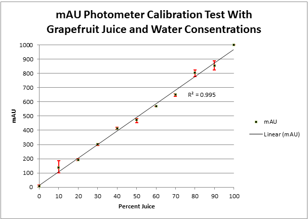
Figure 2:
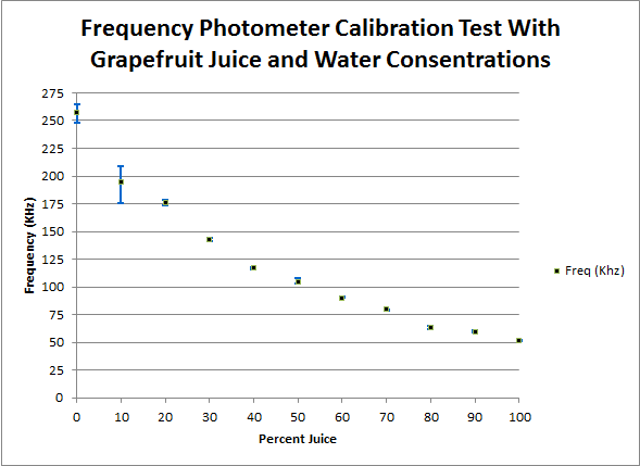
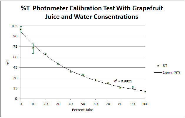
Figure 3:
Results:
Because the milli-absorbance units graph (mAU) is supposed to be linear, the frequency graph is supposed to be logarithmic, and the percent of transmittance graph is supposed to be exponential, the trendlines have a high enough level of similarity to the points (represented by the R2 value*) for this v3 photometer to be considered accurate. The reason why there is no trendline for the frequency graph is because the logarithmic trendline setting would need to be manually adjusted, which defeats the purpose of this test.
Because of the high level of accuracy and the decrease in build time, the v3 photometer has proven that it is an acceptable replacement for the v2.
*The R2 value, often referred to as the goodness of fit, can be computed manually by using this equation:
